







Custom production
Composite parts woven in one piece to your design
Preform weaving, resin transfer and CNC finishing for profiles, beams and connection parts.
A preform woven in one piece
The part is first woven in one piece as a dry fibre preform, on a 3D loom designed and built in-house. Warp (X) yarns run lengthwise and weft (Y) yarns run crosswise. Z yarns (binder yarns) run through the thickness and bind the layers together during weaving. Joints form in the same weave as the rest of the part. They therefore have no bond line and no resin-rich filler zone (noodle).
Profile types
T, Π and H preforms are woven closed (folded flat) on the loom and opened out after they come off the loom to form the section. Drawings are schematic; dimensions, wall thickness and weave pattern are set for each part.
-
T profile
Flange and web form in the same weave; the web yarns continue into the flange without a break. Skin-stiffener joints, beam caps and connection straps.
-
Π profile
Base and both legs are woven in one piece; a plate sits between the legs. Plate-to-plate and plate-to-web joints.
-
H profile
Two flanges and a web in one piece. Beams, frames and rail members.
-
Box profile
Closed section for arms, beams and load-bearing members that need torsional stiffness.
The corner joint of a T profile
In a hand-laid T profile two L plies sit back to back, and under the corner the plies cannot meet: a triangular gap remains, known as the noodle. Under a pull-off load the crack starts there. In 3D weaving the web, corner and base are woven as one piece and the corner is filled with fibre.
The plies are laid: two L plies and a base in 2D, one woven piece in 3D. In 2D a noodle gap remains under the corner; in 3D the corner is filled with fibre. Under the same pull-off load the 2D crack starts at the gap; in 3D web and base carry the load together.
Manufacturing capabilities
- Weave architecture
- In an orthogonal weave, warp and weft stay straight and Z yarns cross the thickness at right angles. In a layer-to-layer interlock, Z yarns bind adjacent layers together; this architecture is woven in both a straight and an angle-interlock version. One part can use different patterns in different zones.
- Geometry
- Cylindrical, conical, variable-thickness and curved preforms are woven in a single operation. A flexible preform takes the shape of the mould during vacuum-assisted resin transfer moulding (VARTM). Curved parts such as propeller blades are made this way.
- CNC finishing
- Custom profiles are woven close to net shape. Thick parts are woven as a billet and the final geometry is machined on CNC; mounting holes are also drilled on CNC. The layers do not separate during drilling, milling or waterjet cutting.
Hybrid structures: a different fibre on each axis
Warp, weft and Z yarns are fed to the loom separately, so each axis can carry a different fibre. The Z yarns bind the different fibres together within one preform; material transitions stay bound through the thickness as well. Besides carbon, glass and aramid, silica and quartz fibres can also be used.
- Carbon
- Stiffness along the load axis.
- Aramid
- Areas that need impact or ballistic resistance.
- Glass
- Uses where cost or electrical insulation comes first.
Fibres differ in stiffness and elongation at break. Fibre and weave pattern are therefore chosen together, based on the part’s loads and service conditions.
Request a quote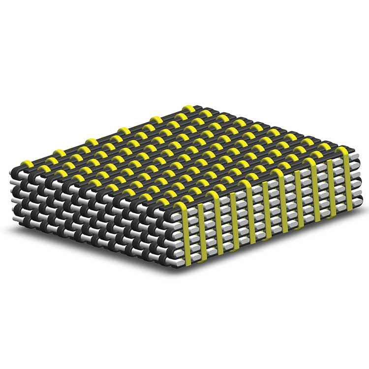
From prototype to series production
The first parts are made as prototypes. The approved weave pattern, mould and process parameters carry over unchanged into series production.
-
Technical file and quote
You send the drawing (STEP, DWG, DXF or PDF), dimensions, load case and quantity. On request, an NDA is signed first. The quote is emailed after a technical review.
-
Weave and material selection
Weave architecture, fibre type, the fibre split between axes and the resin system are set by the part’s load case. Pattern software converts the part’s 3D geometry into the loom’s fibre-bobbin matrix.
-
Preform weaving
The loom is set up and adjusted for each part. The preform is woven in one piece and contains no resin at this stage.
-
Resin transfer and cure
The VARTM mould is designed in-house for the preform and the resin system. The dry preform is placed in the mould. Resin is drawn in under vacuum, impregnates the preform and cures in the mould.
-
Finishing and delivery
The demoulded part is machined on CNC and inspected. Prototype parts are delivered for testing and approval.
Quote request
Send the part drawing, dimensions and quantity. If the load case and tolerances are known, add them to the project details.